

 русский
 Deutsch
 عربى
A dry-running PTFE bearing that survives ten million cycles in one machine can fail inside two hundred thousand in another, and the difference is usually the filler rather than the polymer. Unfilled polytetrafluoroethylene slides against steel at a coefficient of friction of roughly 0.04 to 0.10, yet its wear rate under continuous dry sliding is high enough that virgin parts are rarely specified for moving duty. Almost every PTFE bearing application in service today runs on a compound: PTFE blended with glass fiber, carbon, graphite, bronze, or built on a PEEK base, each shifting friction, load capacity, and cost in a different direction.
Where PTFE Bearings Actually Get Specified
PTFE bearings are chosen where a sliding joint has to run dry, run slowly under heavy load, or survive a medium that destroys grease. The polymer earns its place in five recurring situations.
- Structural slide and pot bearings. Bridge and building bearings use an unfilled PTFE pad confined in a steel recess against polished stainless steel. Design pressure sits at roughly 5 to 10 MPa, and the confined pad is what keeps cold flow within acceptable limits.
- Pump and valve internals. Thrust washers, piston rings, guide bands, and stem bushings work in process fluid, so any grease is washed out within hours. A filled compound runs in that medium with a predictable wear rate instead.
- Dry conveyor and packaging machinery. Slider beds and wear strips on stainless or anodised aluminium need low friction without oil mist reaching the product.
- Cryogenic and aerospace hardware. LNG, oxygen, and fuel system hardware takes PTFE down to about -200 degrees Celsius, while compressor and actuator components use it up to roughly 260 degrees Celsius in air.
- Electrical and semiconductor equipment. Low dielectric loss and low outgassing make PTFE bearing surfaces usable inside insulated assemblies where a metal bush would short or contaminate.
The same polymer serves a 6 MPa bridge pad and a fractional-torque instrument bushing, which is why grade selection matters far more than the material name written on the drawing.
Virgin PTFE versus Filled PTFE: Which One Sets Bearing Life
Filled compounds outlast virgin PTFE by one to three orders of magnitude in dry sliding, and the right filler is decided by the counterface material rather than by the load alone. Filler choice also drives cost, machinability, and chemical compatibility.
A PTFE bearing is a sliding element whose contact surface is polytetrafluoroethylene or a PTFE compound, normally backed by a metal or composite shell that carries the compressive load and conducts frictional heat away from the sliding plane.
Virgin PTFE
- Lowest friction and widest chemical resistance
- Best choice for food contact and electrical insulation
- High wear rate and heavy creep under sustained load
- PV ceiling around 0.1 MPa m/s in dry running
Filled PTFE
- Wear resistance raised by one to three orders of magnitude
- Higher compressive strength and lower creep
- Better heat path through bronze or carbon fillers
- Abrasive or chemically limited fillers need checking
Filler behaviour is not interchangeable. A 25 percent glass fiber grade raises compressive strength and cuts wear sharply, but it will polish a soft aluminium shaft rather than slide on it. Carbon and graphite lower friction and add thermal conductivity, which pays off at higher sliding speed. Bronze carries the highest PV and the best heat path, yet it is unusable in acids and corrodes in wet service. If you want a closer comparison of how material modifications change PTFE wear behaviour, read the compound data before the drawing is released.
Load, Speed and PV Limits to Design Around
The working ceiling of a dry-running PTFE bearing is set by PV, the product of contact pressure in MPa and sliding speed in metres per second, not by load alone. Above that ceiling, frictional heat builds faster than the backing can remove it, surface temperature climbs, and wear accelerates within minutes rather than months.
Those figures are steady-state ceilings for continuous dry running at around 20 degrees Celsius ambient with a metal backing doing the heat removal. Intermittent duty can sit two to three times higher because heat dissipates between strokes. Thin-wall bushings sit at the low end of each range, while a bonded liner on a steel shell can run at roughly double the PV of the same compound machined as a solid part.
Practical check: if a running PTFE bearing feels hot through a gloved hand after ten minutes, the PV is already too high. The polymer keeps its strength to about 120 degrees Celsius, but its wear rate rises well before that point.
Thermal Expansion and Clearance: The Tolerance Problem
PTFE expands roughly ten times more than steel per kelvin, so a 100 mm bearing grows about 1.2 mm across a 100 K swing while the steel housing around it grows 0.12 mm. Copy a clearance figure from a bronze bush and the bearing will close onto its shaft at operating temperature.
| Material | Expansion, 10^-5 per K | Growth over 100 K |
| Unfilled PTFE | 12 to 13 | 1.2 to 1.3 mm |
| Glass or carbon filled PTFE | 6 to 9 | 0.6 to 0.9 mm |
| PEEK composite | 3 to 5 | 0.3 to 0.5 mm |
| Bronze | 1.8 | 0.18 mm |
| Stainless steel | 1.6 to 1.7 | 0.17 mm |
| Carbon steel | 1.2 | 0.12 mm |
Three habits manage the problem. Confine the pad inside a steel recess so expansion is constrained rather than free. Calculate clearance by material pair, not by nominal bore. And switch to a filled grade whenever the temperature swing exceeds roughly 60 K, because glass and carbon fillers cut the expansion coefficient by a third to a half.
Cold flow is the companion issue. Unconfined PTFE at 10 MPa creeps by several percent over months at room temperature, so keeping unit pressure below about 5 MPa unconfined, or about 10 MPa in a confined recess, is what makes a multi-year service life realistic.
Matching Bearing Form to the Application
Form factor matters as much as compound, because the surrounding metal controls heat removal, expansion, and extrusion. A flat pad, a machined sleeve, and a piston ring made from identical filled PTFE behave very differently in the same machine.
| Application | Bearing form | Suggested compound | Main risk |
| Bridge and structural slide | Flat pad plus stainless plate | Unfilled, confined | Creep and grit at the sliding plane |
| Pump thrust face | Washer | Bronze or carbon filled | Filler corrosion in acids |
| Valve stem or trunnion | Sleeve | Glass fiber filled | Shaft scoring on soft metal |
| Hydraulic piston or rod | Guide ring | Carbon-graphite filled | Extrusion into the clearance gap |
| Cryogenic valve | Seat and ball | Unfilled or carbon filled | Contraction of about 1.5 mm over 200 K |
Parts That Match These Duties
Real equipment rarely needs only a flat pad: a slider for linear travel, a ring for a reciprocating piston, and a filled grade for the heat load. The fluoroplastic components below are moulded and machined by Zhejiang Juxiang Fluoroplastics Co., Ltd. in virgin PTFE and in glass, carbon, and bronze filled compounds.
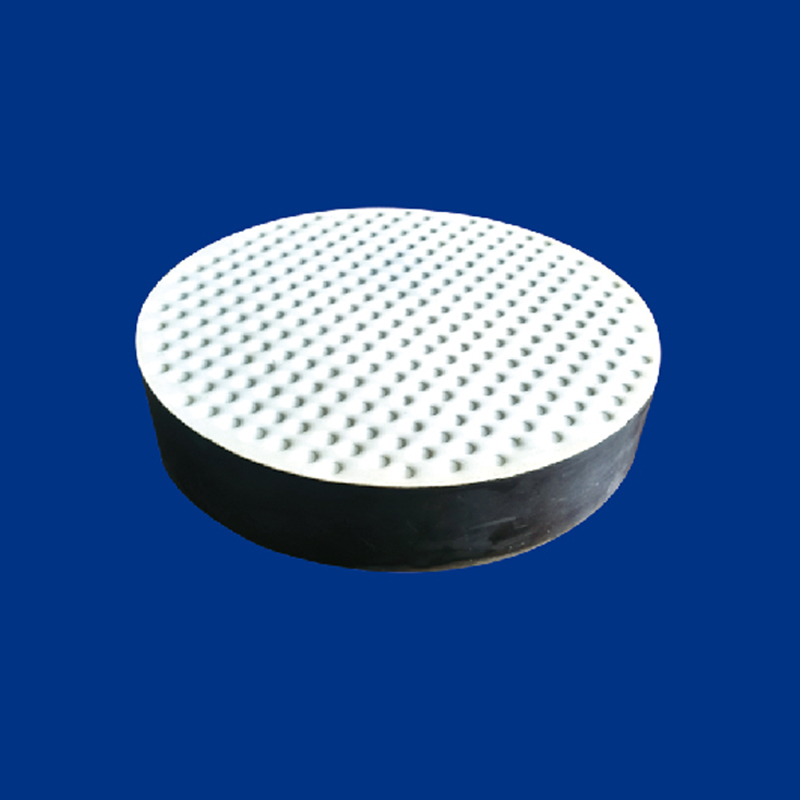 PTFE Bearing Slider for Low-Friction Structural ApplicationsA molded and machined PTFE sliding pad for bridge bearings, rockers and plant sliders, offered in virgin or filled grades to drawing.View Product →
 PTFE Piston Rings for Hydraulic and Pneumatic CylindersCategory of virgin, modified and filled PTFE piston rings for cylinders, compressors, pumps and valves, with standard references and custom sizes to drawing.View Product →
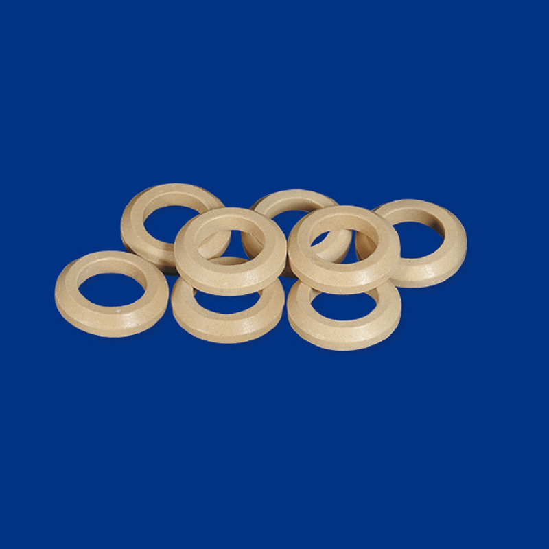 PHBA-Filled PTFE Compound for High-Load ComponentsPHBA-filled PTFE supplied as rod, tube, sheet and machined parts for high-temperature bearings, bearing pads, sliders, piston rings, gaskets and valve components.View Product →
Specify the compound, the counterface material, and the expected PV in the same document. Suppliers who receive all three can machine to the correct clearance the first time, while buyers who leave the filler open often receive whichever grade is cheapest to press that week.
Failure Patterns and How to Design Them Out
Most PTFE bearing failures in the field trace back to five predictable causes, and each one has a design answer that costs far less than a premature replacement.
- Grit embedding. PTFE is softer than the debris around it, so sand and metal fines press into the pad and turn it into a lapping tool. Fit a wiper lip or seal the sliding gap.
- Extrusion into the clearance. A gap wider than about 0.5 mm lets the pad flow under high pressure. Reduce the gap or add an anti-extrusion ring.
- Counterface finish. Roughness above about 0.8 micron accelerates wear, while a finish below 0.1 micron can produce stick-slip on very slow movements. Aim for 0.2 to 0.4 micron on hardened steel.
- Filler corrosion. Bronze-filled parts in acid service lose the bronze phase and leave a porous PTFE skeleton behind. Switch to carbon or graphite for chemical duty.
- Bonding failure on lined parts. PTFE does not bond without etching or sodium treatment, and an untreated surface releases under thermal cycling.
Frequently Asked Questions
What load can a PTFE bearing carry?
A confined flat pad is normally designed at 5 to 10 MPa. Compressive strength is far higher, around 20 to 30 MPa at 10 percent strain, but creep rather than strength governs the design, so sustained unit pressure is the real limit.
Do PTFE bearings really run without grease?
Yes. Unfilled PTFE on polished steel gives a dry friction coefficient of 0.04 to 0.10, and filled grades stay below 0.20 while carrying much higher PV. Lubricant is added only to flush contamination or to help heat removal at higher speed.
Which filler works with a stainless steel shaft?
Glass fiber at 15 to 25 percent suits hardened stainless above roughly 200 HV, because the filler cannot score that surface. Avoid glass-filled grades on soft aluminium or mild steel, where carbon or graphite compounds are the safer match.
How much clearance should be allowed for thermal expansion?
Allow roughly 0.4 to 0.6 mm of diametral clearance per 100 mm of bore for a 100 K rise, calculated from the actual filler grade rather than from unfilled PTFE. A confined pad design removes most of the problem because the steel recess holds expansion in check.