

 русский
 Deutsch
 عربى


PTFE Steel-Plastic Component Pipe from Gansu Juxiang
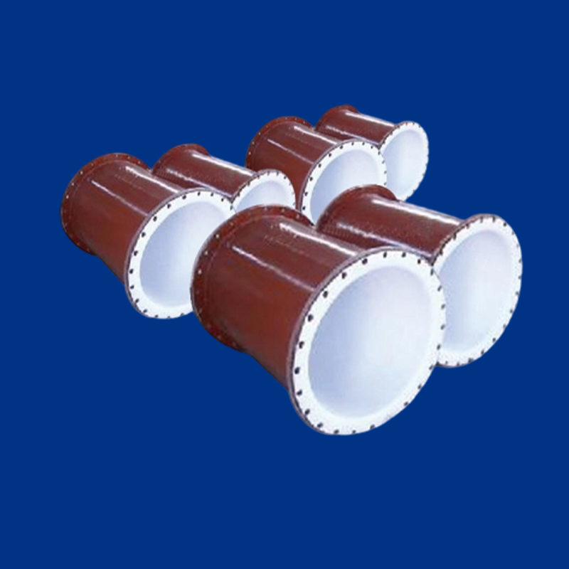
Gansu Juxiang Fluoroplastics Technology Co.,Ltd. produces PTFE Steel-Plastic Component Pipe manufacturer output in Yumen City, Gansu Province, within a fluoroplastics operation that also runs a production base in Zhejiang. The product is a composite pipe: a ram-extruded PTFE liner is tightened into a steel shell so the two materials act together under pressure, vacuum and thermal cycling.
The range serves chemical and petrochemical transfer lines where hot corrosive media would attack bare steel or contaminate product through a metal wetted surface. Standard nominal diameters run from DN25 to DN200, liner thickness from 3.5 mm to 4.5 mm, and finished spools to 4000 mm. Flange size, drilling, face finish and installed length follow the project drawing rather than a fixed catalogue.
- Temperature range: -60 °C to +260 °C
- Positive pressure: 1.6 MPa
- Vacuum: 77 kPa
- Nominal sizes: DN25 (1") to DN200 (8")
- Maximum spool length: 4000 mm
Construction and Position in the Fluoroplastic Range
The liner is produced by ram extrusion, which gives a dense, uniform PTFE wall without the seams of a wrapped or welded liner. That wall is the wetted surface; the steel shell carries external loads and holds the liner against collapse in vacuum service. The tightening step is the critical one — if the liner is not seated correctly, vacuum capability is lost and the liner can creep under thermal cycling.
Within our fluoroplastic range, this pipe belongs to the wetted-path group for aggressive fluid handling, alongside PTFE lined valves and gaskets. Where a line needs a fully fluoropolymer wetted surface and the mechanical strength of metal, the steel-plastic composite is the appropriate construction. Solid PTFE pipe remains an option where pressure and support conditions allow it.
- Steel shell provides rigidity, impact resistance and support for the liner
- PTFE liner isolates the steel from acid, alkali and oxidising media
- Composite construction keeps the pressure boundary metallic
- Flange-to-flange dimensions can be matched to existing pipework
Standard Dimensional Envelope
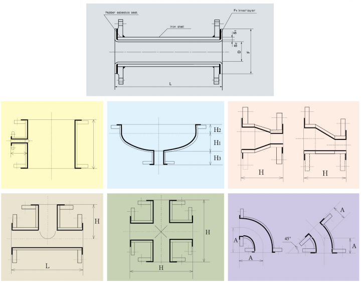
Dimensions are set by nominal size. S1 is the PTFE liner wall, S2 the steel wall, D the bore, F the minimum flange outside diameter and L the maximum spool length.
| Nominal size | S1 liner (mm) | S2 steel (mm) | D bore (mm) | F min. flange OD (mm) | L max. (mm) |
|---|---|---|---|---|---|
| DN25 (1") | 3.5 | 2 | 21 | ≥55 | ≤4000 |
| DN32 (1¼") | 3.5 / 4 | 2 | 28 | ≥68 | ≤4000 |
| DN40 (1½") | 3.5 | 2 | 36 | ≥80 | ≤4000 |
| DN50 (2") | 4 | 2 | 46 | ≥90 | ≤4000 |
| DN65 (2½") | 4.5 | 2.5 | 60 | ≥105 | ≤4000 |
| DN80 (3") | 4.5 | 2.5 | 75 | ≥125 | ≤4000 |
| DN100 (4") | 4.5 | 3 | 94 | ≥150 | ≤4000 |
| DN125 (5") | 4.5 | 3.5 / 4 | 117 | ≥185 | ≤4000 |
| DN150 (6") | 4.5 | 4 | 142 | ≥215 | ≤4000 |
| DN200 (8") | 4.5 | 4 / 4.5 | 191 | ≥280 | ≤4000 |
Liner and steel wall are selected together. A thicker liner gives more corrosion allowance and better vacuum stability; a thicker steel wall raises external stiffness and allows wider support spacing. The F value is a minimum and must be respected when matching to existing pipework.
Application Fit by Duty
Duty conditions decide the wall combination and the joint detail more than nominal size does. Three service patterns account for most of the pipe we make.
Positive-pressure corrosive liquid
Acid, alkali and brine transfer at up to 1.6 MPa is the base case. The PTFE liner isolates the steel from the medium, so the pipe handles hydrochloric acid, sulphuric acid and chlor-alkali liquors that would otherwise require alloy pipe.
Vacuum and vapour service
At 77 kPa vacuum the liner must stay tight against the steel; this is where the tightening process matters most. Vacuum distillation, tank draw-off and vapour recovery lines are typical duties.
High-temperature gas and thermal cycling
At the upper end of the -60 °C to +260 °C range, differential expansion between PTFE and steel becomes the design issue. Longer spools need expansion allowance and supports that do not pinch the liner at the flange.
Connection, Fabrication and Line Integration
Spools are supplied flanged to the project standard, with gasket and bolt-up detail agreed at order. For flange joints we supply modified PTFE gaskets and expanded PTFE reinforced flange gaskets from the same fluoroplastic range, so the wetted path stays consistent from pipe to gasket.
- Flange standard, size and pressure class
- Face finish: raised face or full face
- Gasket type and thickness
- Bolt material and tightening sequence
- Support and hanger locations
- Expansion loops or flexible elements
Bends, tees, reducers and short spools are fabricated to drawing. We check wetted-surface continuity at every joint, because a lined component that is correct in isolation can still leave a step or gap at the flange face.
Quality Control and Acceptance
Production starts with the liner: ram-extruded tube is checked for wall thickness and surface defects before it enters the steel shell. After tightening, the spool is checked for bore, overall length, flange face and end liner thickness. Pressure and vacuum verification follows the values specified for the line.
- Liner wall thickness and surface condition
- Bore, squareness and installed length
- Flange drilling, facing and liner termination
- Pressure and vacuum performance at the specified rating
Documentation is compiled against the inspection plan agreed at order stage and travels with the shipment. Where a project uses its own inspection and test plan format, we align the record before production begins.
Information We Use to Configure Your Solution
A line list or marked-up drawing is enough to start. The inputs below determine the wall combination, flange detail and gasket selection.
| Project input | What it determines |
|---|---|
| Medium and concentration | Liner grade and gasket selection |
| Operating temperature, minimum and maximum | Expansion allowance and material limits |
| Pressure and vacuum condition | S1/S2 combination and flange class |
| Nominal diameter and installed length | Spool configuration and support spacing |
| Flange standard, size and facing | Matching to existing pipework |
| Gasket and bolt specification | Joint integrity and tightening data |
| Orientation and support arrangement | Stress at flanges and liner terminations |
| Quantity and delivery sequence | Production planning and packing |
Where the line already exists, we work from flange-to-flange dimensions plus a sketch or photograph of the connection. For new builds, the piping isometric and the medium data sheet give us what is needed to issue a configuration and quotation.
Frequently Asked Questions
What pressure and vacuum can the pipe handle?
The standard rating is 1.6 MPa positive pressure and 77 kPa vacuum across the -60 °C to +260 °C range. Where a duty sits at the top of the temperature range or combines vacuum with thermal cycling, we review the wall combination before confirming the configuration.
Can you produce non-standard lengths and flange drilling?
Yes. Spools are made to drawing up to 4000 mm, with flange size, drilling pattern, face finish and installed length set by the project. We work from isometrics, line lists or existing flange-to-flange measurements.
How is the PTFE liner fixed inside the steel pipe?
The liner is a ram-extruded PTFE tube tightened into the steel shell by a dedicated process, so it stays in contact with the steel under pressure and vacuum. It is not a loose liner that relies on the medium to hold it in place.
What is needed for a quotation?
Send the medium, concentration, operating temperature, pressure or vacuum condition, nominal diameter, installed length, flange standard and quantity. A drawing or line list is sufficient for us to propose the wall combination, gasket detail and delivery scope.
Related Products and Categories
Our portfolio also includes Products for applications with different operating ranges, interfaces or integration requirements.